PCB:
PCB Stands for "Printed Circuit Board." A PCB is a thin board made of fiberglass, composite epoxy, or other laminate material. Conductive pathways are etched or "printed" onto board, connecting different components on the PCB, such as transistors, resistors, and integrated circuits.


BE POSITIVE

Schematic Diagram: graphical or symbolic representation of a circuit diagram.

Annular Ring: Conductive material surrounding a hole which creates a pad.

Solder Mask: A coating applied to a circuit board to prevent solder from flowing onto any areas where it`s not desired or from bridging across closely spaced conductors.(Fig 1.0)
Aspect Ratio: The ratio of the circuit board thickness to the smallest drilled hole diameter.
(Fig 2.0)

(Fig 2.0)

Assembly drawing: A drawing showing the locations of components, with their reference designators, on a printed circuit. Also called component locator drawing.


Bed-of-Nails: A method of testing printed circuit boards that employs a test figure mounting an array of contact pins configured so as to engage plated thru-holes on the board.


Conformal coating: An insulated protective coating that conforms to the components and is applied on the completed board assembly.


Dielectric: An insulating medium, which occupies the region between two or more conductors.


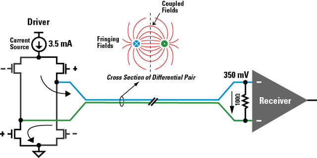
Differential signal: A method of signal transmission through two wires which always have opposite states. The signal data is the polarity difference between the wires.

Why ? Differential Pair !
CASE 1:
SOURCE (VOLTAGE):-
EXAMPLE:


CASE 2
SOURCE(CURRENT):-
EXAMPLE:

Why ? Differential Pair !
CASE 1:
SOURCE (VOLTAGE):-
EXAMPLE:


SOURCE(CURRENT):-
EXAMPLE:

Etch: Chemical removal of metal (copper) to achieve a desired circuit pattern.


Fabrication drawing: A drawing used to aid the construction of a printed board. It shows all of the locations of the holes to be drilled, their sizes and tolerances, dimensions of the board edges, and notes on the materials and methods to be used. Called "fab drawing" for short.


Fiducial: Etched features or drilled hole used for optical alignment during assembly operations.

Types of Fiducial : There are two types of fiducial markers commonly found in printed circuit board designs: global fiducial markers and local fiducial markers. Global fiducial markers are a copper reference placed on the edge of the PCB that allows the machine to determine the orientation of the board with respect to the X-Y axis.


Types of Fiducial : There are two types of fiducial markers commonly found in printed circuit board designs: global fiducial markers and local fiducial markers. Global fiducial markers are a copper reference placed on the edge of the PCB that allows the machine to determine the orientation of the board with respect to the X-Y axis.

Pitch: The nominal distance between the centers of adjacent features or traces on any layer of a printed circuit board.

Fine pitch: Refers to chip packages with lead pitches below 1 mm.

Finger: A gold-plated terminal of a card-edge connector.


Ground Plane: A conductor layer, or portion of a conductor layer, used as a common reference point for circuit returns, shielding, or heat sinking.


IPC: The Institute for Interconnecting and Packaging Electronic Circuits.
Mil: One-thousandth of an inch 0.001:" (0.0254 mm).
Minimum Annular Ring: The minimum metal width, at the narrowest point, between the circumference of the hole and the outer circumference of the land.
Netlist: List of names of symbols or parts and their connection points which are logically connected in each net of a circuit.
Pad: The portion of the conductive pattern on printed circuits designated for the mounting or attachment of components. Also called Land.
Plating: Chemical or electromechanical deposition of metal on a pattern.


Pre-preg: semi cured adhesive material used in multi layers PCB.


Resist: Coating material used to mask or to protect selected areas of a pattern from the action of an etchant, solder, or plating.


Via: A plated thru-hole that is used as an inner-layer connection but doesn`t have component lead or other reinforcing material in it. Vias can make an electrical connection between layers on a PCB.


Plated-Through Hole: (PTH) A hole in a circuit board that that been plated with metal (usually copper) on its sides to provide electrical connections between conductive patterns layers of a printed circuit board.
Microvia: A via used to make connection between two adjacent layers, typically less than 6 mils in diameter. May be formed by laser ablation, plasma etching, or photo processing.
Blind Via Hole: A plated-through hole connecting an outer layer to one or more internal conductor layers of a multilayer printed board but not extending fully through all of the layers of base material of the board.


Buried vias: A plated-through hole connecting an internal layer to one or more internal conductor layers.
Tented via: A via with dry film solder mask completely covering both its pad and its plated-thru hole. This completely insulates the via from foreign objects, thus protecting against accidental shorts.
Tented via: A via with dry film solder mask completely covering both its pad and its plated-thru hole. This completely insulates the via from foreign objects, thus protecting against accidental shorts.
Stacked vias: Micro vias in HDI(high density interconnect) PCB, that are stacked one upon each other.


----------------------------------------------------------------------------------------------------------
Types of transmission line

Stripe Line:
"an electrical layer in between reference layer."


Micro stripe line :
"an electrical on the top with a reference on the bottom."


Types of layer technology
Laminate technology:
"Stacked up with laminate in between pre-preg."
Laminate:
"It also know as core, It has copper on both side insulated by dielectric material in between."
Foil technology:
"Stacked up with top and bottom layer of foil and in between layers with laminate."
Foil:
'It’s a copper sheet."
Types of board finishing
HASL: Hot Air Leveling
OSP: Organic solder-ability Preservative
ENIG: Electro less nickel immersion gold
INS- Immersion tin Standards
IPC series from 2220 to 7351 are followed.
Hi. I’m Designer of Blog TECHNO. I’m CEO/Founder of TECHNO. I’m Creative Art Director, PCB Designer, Web Designer,Web Developer, Business Enthusiast, StartUp Enthusiast, Speaker, Writer. Inspired to make things looks better.
0 comments:
Post a Comment